Some Known Questions About Geospatial Solutions.
Wiki Article
The Facts About Drone Imagery Services Revealed
Table of ContentsHow Geospatial Solutions can Save You Time, Stress, and Money.The Facts About Ground Control Points Uncovered7 Simple Techniques For Ground Control PointsNot known Details About Ground Control Points Examine This Report on Ground Control Points
Advised features include converging street paint striping, road corners, or various other natural or industrialized features on the ground. To manually choose as well as gauge GCPs from a reference picture to support the adjustment process, finish the following actions: Add the reference photo to the 2D map view. Note the VCS of the DEM utilized to support the procedure.This dialog box is made use of to define upright changes that may be called for to accurately transform elevations removed from the elevation surface connected with the work space into the spatial referencing of the job. Click the Browse switch. On the Spatial Reference dialog box, click in the Vertical Coordinate System (VCS) box below Present Z, and also select the VCS of the DEM connected to the picture collection.
This makes sure that GCPs are picked from the referral photo. In the GCP Supervisor home window, click the Include GCP or Connection Factor switch.
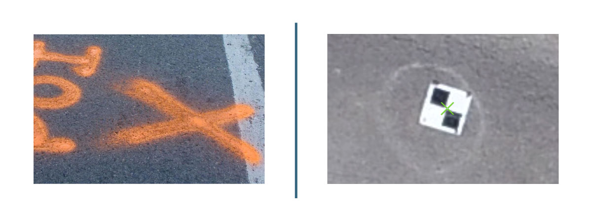
Surf to a recognizable feature in the reference imagery that you want to collect as a GCP, and also click it. A red cross shows up over the attribute on the map and also a new GCP access is entered in the GCP Manager. In the GCP Manager window, find the equivalent GCP function in the picture customer as well as click the function to put a tie point.
The Ultimate Guide To Ground Control Points
As soon as a tie point has actually been successfully included in a photo, the gray tie point sign adjustments to blue in the image viewer and in the 2D map, and the GCP icon modifications from red to green. This indicates that the GCP has been gauged. To change or remeasure the location of a gauged factor, click the point.If including a one-dimensional (1D) coordinate, go into the elevation value in the Z field as well as established the XY Accuracy area worth to NA. Optionally, input the GCP Z Precision value. If getting in a two-dimensional (2D) coordinate, include the X and also Y works with to the proper areas and set the Z Precision area worth to NA.
In cases when an image in the overlapping photo list was not automatically measured, indicated when the + mark did not alter to blue, the image requires to be selected and also the GCP place manually gauged. The location of a measured factor can be transformed by clicking a various location in the photo.
If you do not have GCPs from ground study, but you have an orthorectified photo basemap as a raster layer (raster dataset, mosaic dataset, or image service), you can include it as a reference to calculate GCPs (drone imagery services). When selecting a reference photo for GCP computation, guarantee that the reference picture has great georeferencing top quality in terms of geopositional accuracy as well as clarity and also that the resolution resembles the resource images.
Geospatial Solutions Fundamentals Explained

The corresponding images that overlap with the GCP show up in the picture listing at the bottom of the GCP Manager home window. Click the Include GCP or Connection Point switch to include a photo connection point in the photo audience for each overlapping image.
However, they are not used as inputs to control the modification process. Instead, check points gauge the precision of the modification as well as the resulting orthoimage. For every check point, the range in between its recognized ground location and also the place of the corresponding pixel after the modification process is made use of to compute the general absolute precision of the block of pictures.
Indicators on Geospatial Solutions You Should Know
You can transform GCPs to examine factors for postprocessing precision analysis (drone imagery services). After the GCPs have actually been added and measured with tie points in the Reality mapping work area, select the GCP to change to a check point in the GCP Supervisor home window. Right-click the GCP and also click Modification to Examine Factor.When you add GCPs or connect points, you should click Adapt to rerun the block change and also make use of these factors. Keep the complying with in mind when collaborating with GCPs: Use the Clear Links switch to delete all tie points linked with chosen GCPs. To erase a single connection factor, right-click the picture name in the GCP Manager image viewer and also choose Erase ground control points Tie Factor.
2D GCPs added in a CSV data need to comply with the layout below. 1D GCP's can not be included to a CSV data. Instead, include 1D GCPs using the operations defined in Add GCPs manually area above, steps 6-9. If the GCPs and also the elevation source of the mosaic dataset have various z-values, the images may appear shifted in the map view after adjustment.
Select a GCP from the checklist. The corresponding photos that overlap with the GCP appear in the photo listing at the base of the GCP Manager home window. Click the Include GCP or Tie Factor switch to add a photo connection point in the picture viewer for each and every overlapping image. The connection factors for other pictures are instantly determined when feasible, but review each connection factor for place precision.
The Basic Principles Of Geospatial Solutions
They are not utilized as inputs to regulate the change procedure. Rather, check points measure the precision of the adjustment and the resulting orthoimage. For each check point, the distance between its recognized ground place and the area of the corresponding pixel after the change process is made use of to calculate the overall outright accuracy of the block of pictures.You can change GCPs to inspect factors for postprocessing accuracy evaluation. After the GCPs have actually been added as well as gauged with tie factors in the Reality mapping office, pick the GCP to change to a check point in the GCP Supervisor home window. Right-click the GCP as well as click Adjustment to Examine Factor.
As soon as you include GCPs or tie factors, you should click Get used to rerun the block change and use these points. Maintain the following in mind when dealing with GCPs: Use the Clear Links button to remove all tie factors associated with picked GCPs. To erase a solitary connection point, right-click the image name in the GCP Manager picture visitor and select Erase Connection Factor - Geospatial solutions.
Report this wiki page